KNIFES (SK)
Rozcestník KNIFE príspevkov.
KNIFE-000 - Generation of initial docusaurus from limited data
- make build
- vercel docusaurus KNIFES website deployment setup from https://github.com/iairu/ST-016-OndrejSpanik to https://st-016-ondrej-spanik.vercel.app/
KNIFE-001 - Fritzing installation complication
- initial installation: yay -S fritzing
- custom fritzing patch for DFPlayer + ATTiny86 components and any additional components patched in on the fly by Claude
- started repository for PCB related things: https://github.com/iairu/ST-016-MOTHERBOARD (this session:
ST-017-MOTHERBOARD) - boards are generated, not drawn:
.fzzbuild/build_vN.py(schematic + breadboard) →variant_vN.py+build_pcb_v2.py(placement, routing, ground pour) → Fritzing Gerber export, verified bypcbcheck.py/gerbercheck.py(copper nets vs schematic netlist) andsimcheck_vN.py(breadboard vs schematic nets) - patched Fritzing simulator in
fritzing-sim/plays the DFPlayer'ssound filethrough the speaker while it is driven (ngspice cannot decode MP3) - Gerbers are exported with Fritzing 1.0.1: open the .fzz in 1.0.8, run DRC and re-export before ordering a board
KNIFE-002 - 2026-09-28
- updated v4_parts.md into v5_parts.md by changing the shop from techfun.sk to https://www.tme.eu/ which has a much larger supply of parts so that i can pick the best ones
- trying to simulate the breadboard by hitting simulate button ended up with fritzing giving a segfault due to missing SPICEs
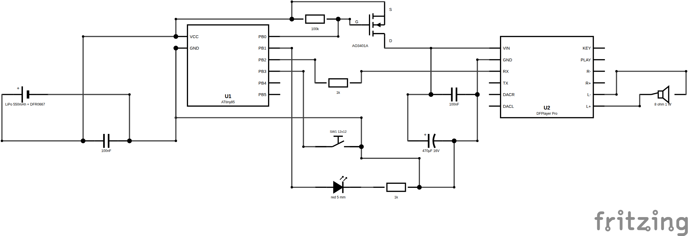
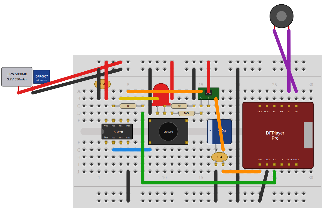
- fixed (v5, 09-28): every part got a SPICE model (ATtiny85 and DFPlayer models copy the firmware's/module's pin behaviour); simulation shows EN 0.05 V, Q1 on, DFPlayer 3.70 V, speaker 1.3 V, LED 1.6 mA
- breadboard image is missing below the breadboard components
- fixed (v5): all parts plugged into a half breadboard,
simcheck_v5.pyconfirms the same 11 nets as the schematic; v6/v7 repeat this (5 and 6 nets)
- fixed (v5): all parts plugged into a half breadboard,
- the board is showing smoke on the battery regardless if button is pressed or released
- fixed (09-30): J1 pin order was inverted against Fritzing's core battery; now connector0 = −, connector1 = +, 0.1 Ω internal resistance. Pads unchanged, so PCB and Gerbers are identical
- use a different background color than wiring color on pcb as wires are not immediately visible right now
- fixed (09-30): ground fills dark green (top) / dark blue (bottom)
- TME has no Digispark, no NDP6020P (withdrawn), no ~30 x 30 mm LiPo and only withdrawn USB-C chargers → v5 swaps: bare ATtiny85 DIP-8 + socket, AO3401A SOT-23, Akyga 503040 550 mAh, DFR0667 micro-USB charger, Visaton K 40 1 W speaker
- v5 side effects: no Digispark regulator/power LED/USB zeners/1.5 kΩ pull-up leaking from the LiPo (better standby), no USB back-feed; costs a programmer (Pololu 19.51 USD, or free Arduino-as-ISP)
- version table and cost comparison: KNIFE-006 · TME prices read 2026-09-28 (USD, net, 1 pc): total ≈ 34 USD + ATtiny85
v5 schematic, breadboard (simulated) and PCB

KNIFE-003 - 2026-09-27 - PCB v1 → v4: shrink, harden, fit the bird
- v1 (
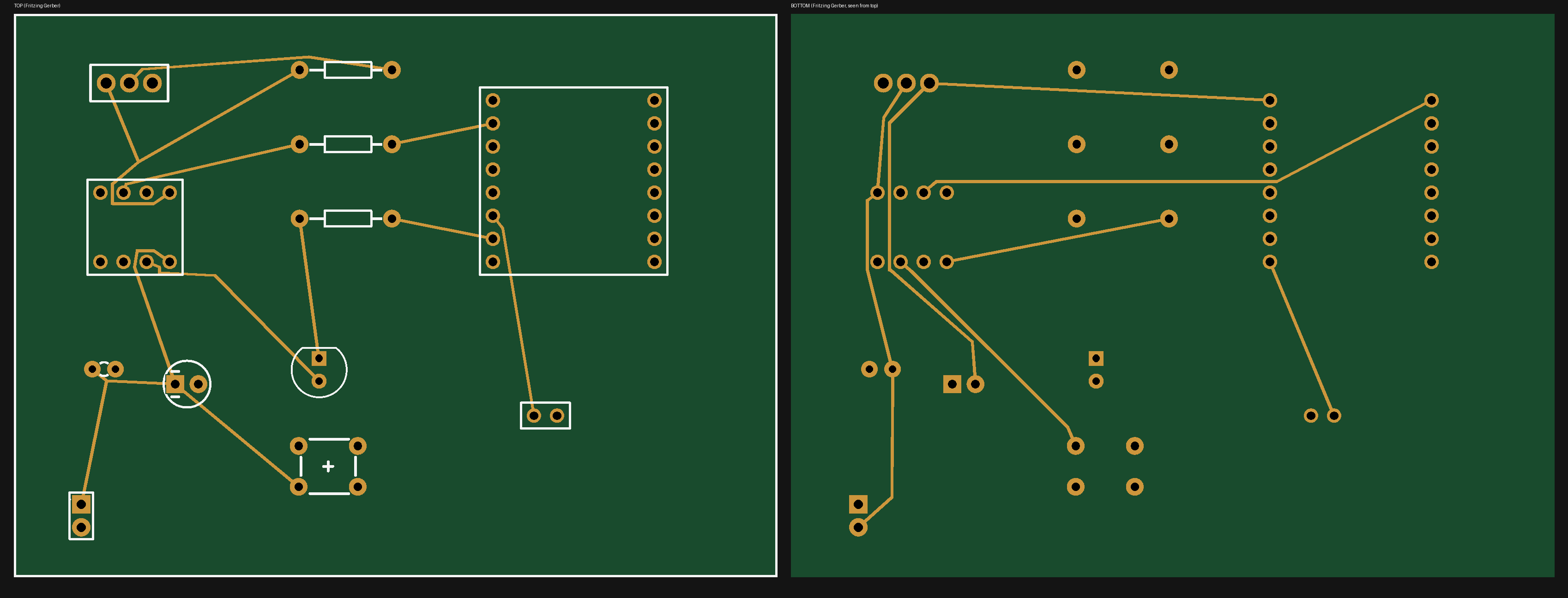
LELEK_board_final, "final version before fab test"): 84.0 x 62.0 mm (5208 mm²), DFPlayer Mini + ATtiny85 + AO3401A + 16340 cell. Independent review found ATtiny RESET floating (resets on any dip below ~40 % Vcc, next to a MOSFET load and DFPlayer turn-on transients) and no DFPlayer decoupling - v2: compact 52 x 37 mm (1924 mm², −63 %), routed 16/24 mil traces, 12 mil min clearance, GND pour on both layers with thermal reliefs, decoupling next to pins, refdes silkscreen. + R4 10 kΩ RST pull-up, + C3 100 nF across DFPlayer VCC. Routing/checking tooling written (
pcbroute.py,pcbcheck.py,gerbercheck.py) - v3: same netlist re-laid out as a 78.1 x 26.7 mm strip (2085 mm²) to fit the bird's belly; LIR2450 coin-cell holder, C2 470 µF, SW1 on the centre line under the button; Gerbers 12/12 nets. Sleep firmware (power-down, MOSFET-switched DFPlayer, TX/BUSY low while off, 3.3 V cut-off). First CNC Nightjar enclosure (two halves, 2.5D pockets, dowels, pry notches, captive wooden button, build guide PDF)
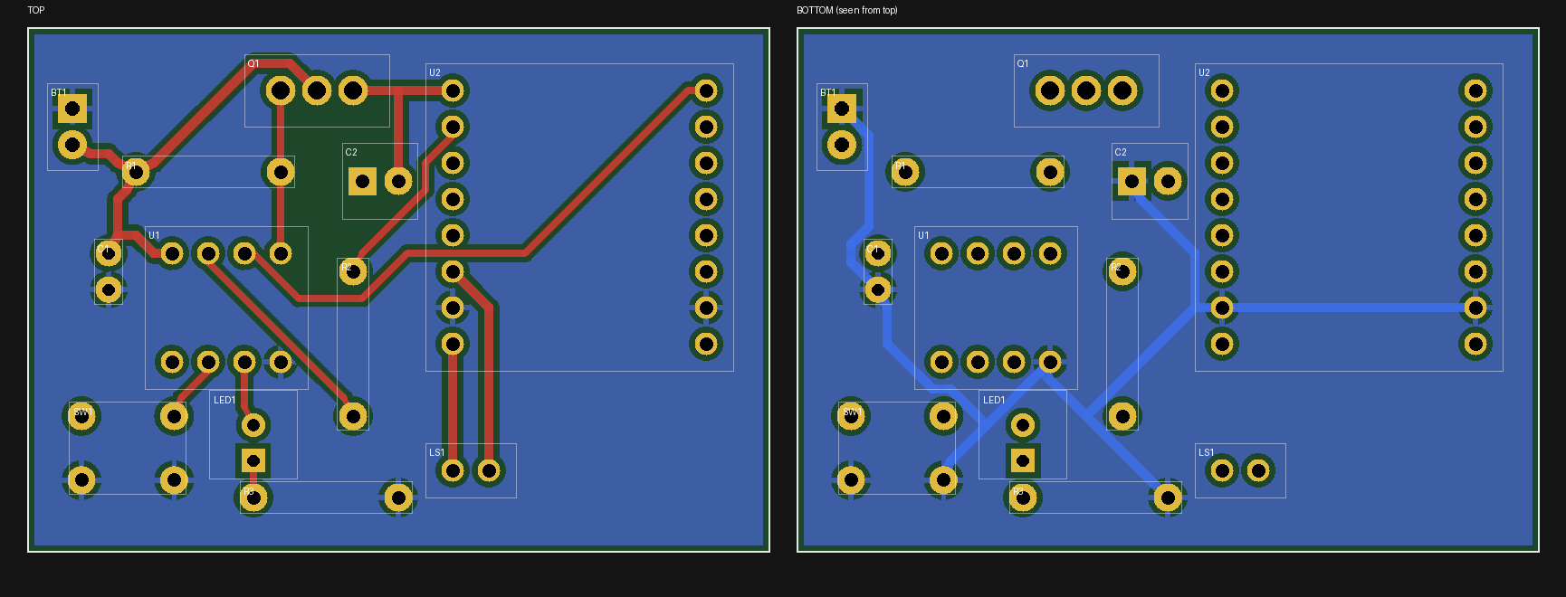
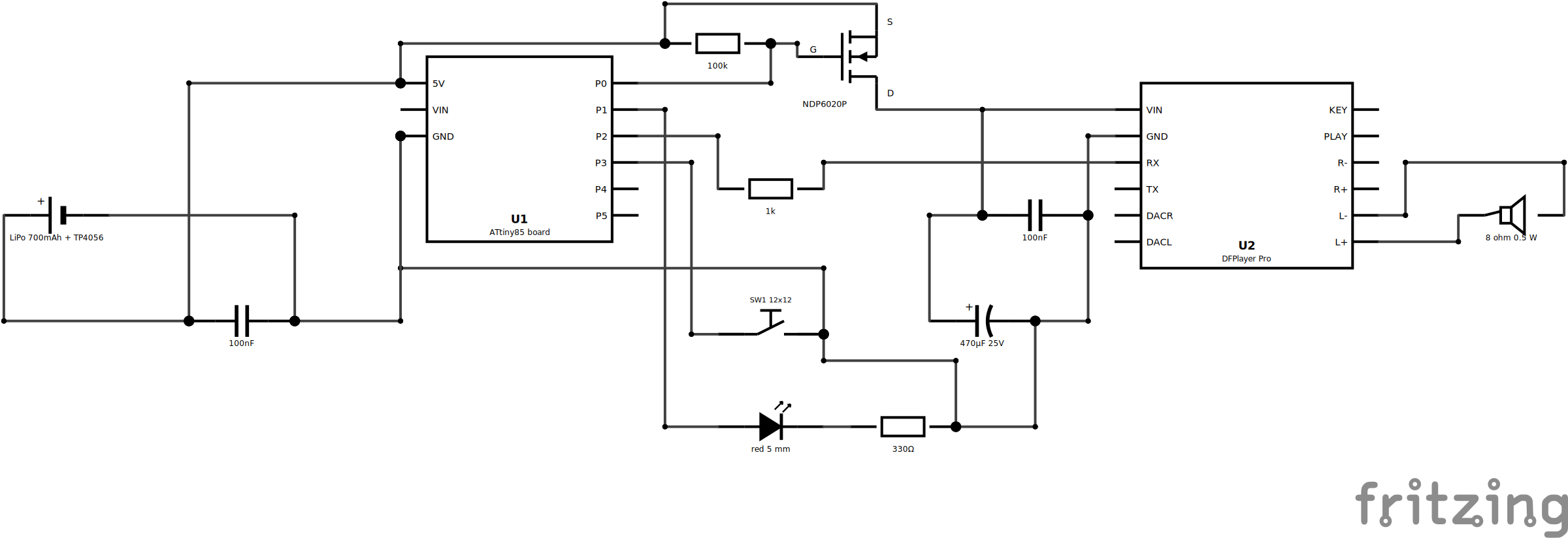
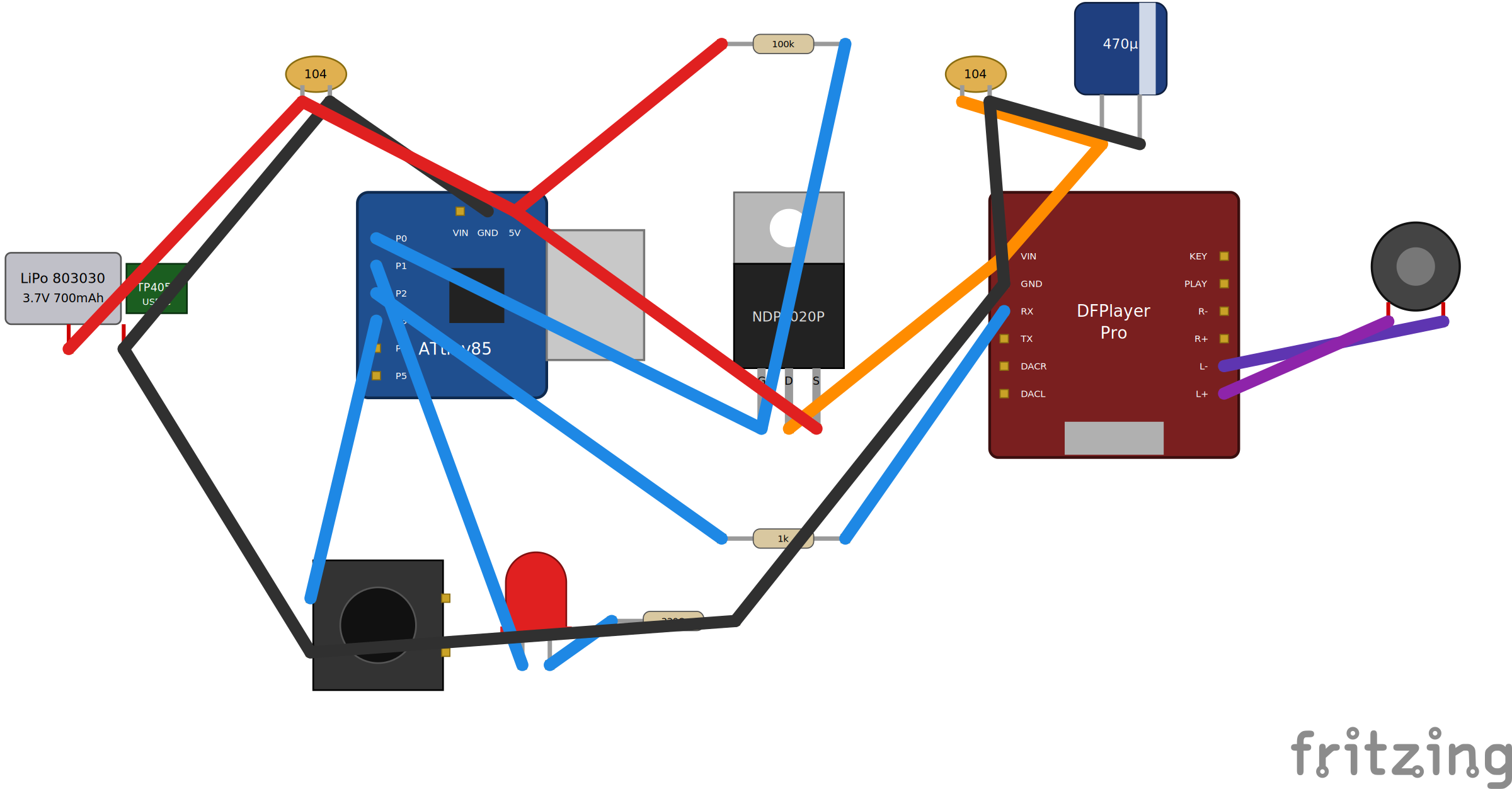
- v4 (techfun.sk): 89.4 x 27.9 mm (2494 mm²). techfun.sk sells no LIR2450 and no AO3401A → 700 mAh LiPo 803030 + TP4056 USB-C charger, NDP6020P TO-220 (only P-MOSFET in stock). Digispark ATtiny85 board replaces the bare chip, DFPlayer Pro (AT commands, 115200 baud, built-in amp, 128 MB flash) replaces the Mini → new firmware. Enclosure re-cut: LiPo pocket under the board, charger pocket + USB-C channel at the tail, walls ≥ 6 mm
- v4 caveats found while writing the parts list: USB 5 V back-feeds the LiPo (5V pin / MOSFET body diode), Digispark power LED drains the battery, P3 zener + 1.5 kΩ pull-up leak above 3.6 V, Q1 lies under U2 (needs ≥ 8.5 mm headers) → all removed by the v5 bare-chip design (KNIFE-002)
- lesson: automated routing + independent Gerber netlist check caught what visual review did not; shop stock drove three of four redesigns
PCB v1, v2, v3 and v4; v4 schematic and breadboard


KNIFE-004 - 2026-10-01 - v6: remove the microcontroller
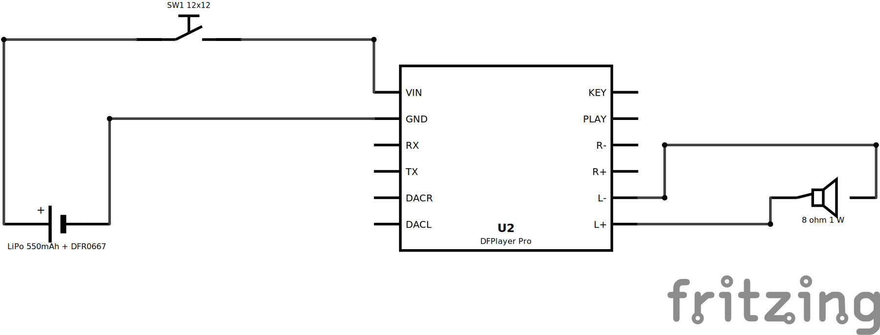
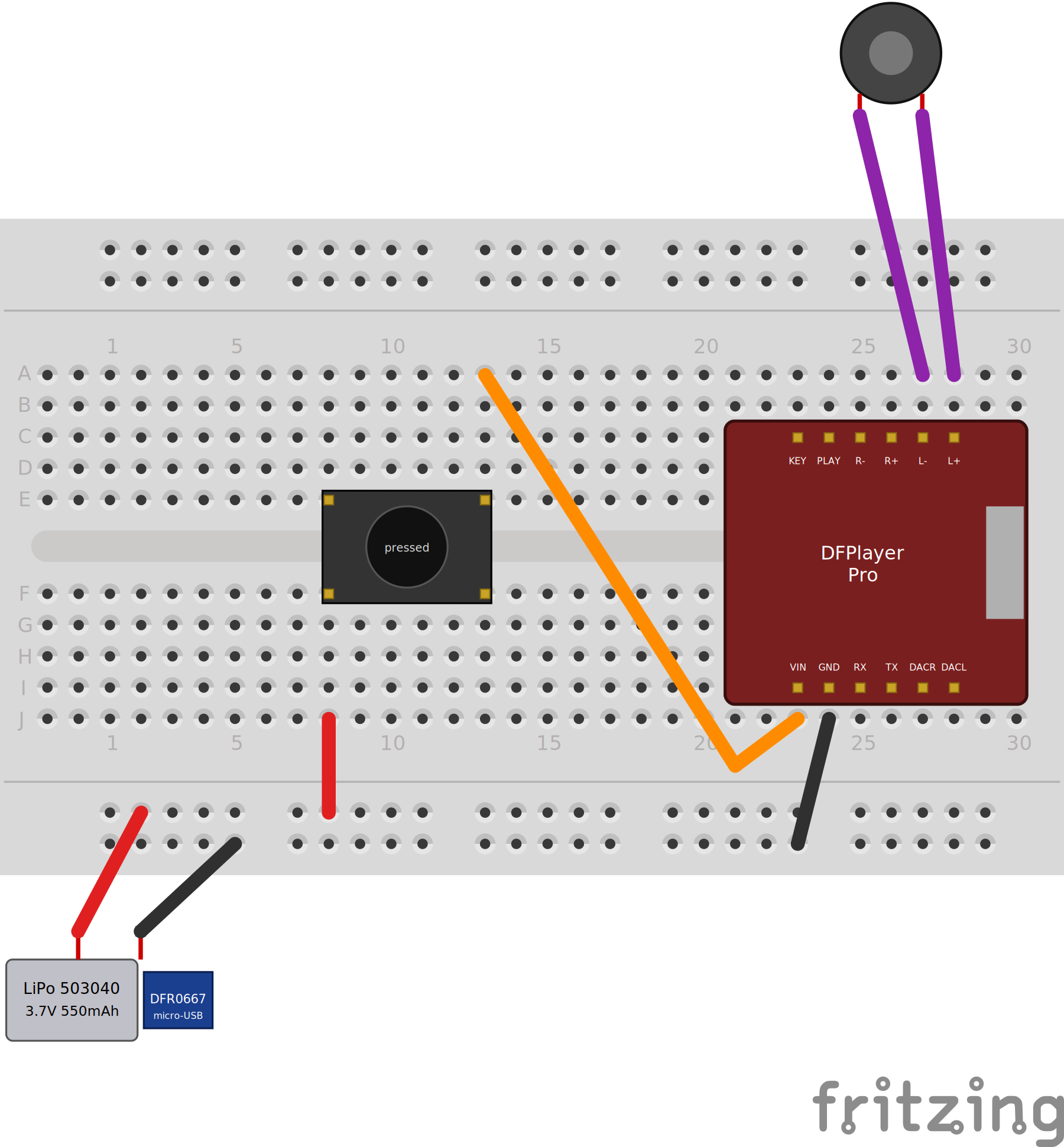
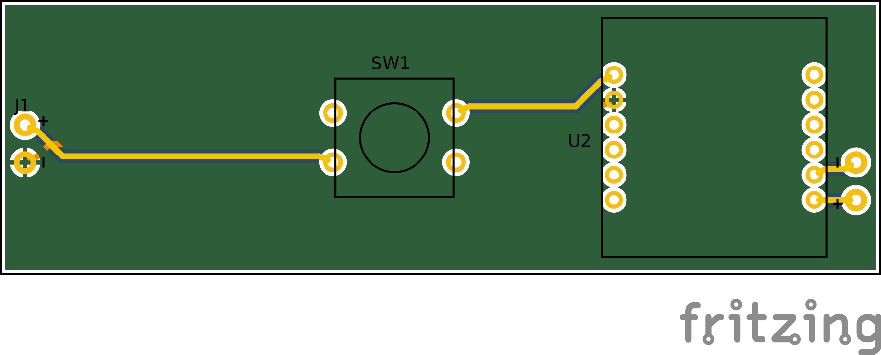
- v5 had 13 board parts to do one thing: gate power to the player. DFPlayer Pro starts playing on boot, so a button in the battery line replaces ATtiny85, socket, AO3401A, 3 resistors, 2 caps, LED, firmware and programmer (9 fewer parts)
- first try (d4a6cb1): button pulls the player's PLAY pin low, battery wired straight to the module → player idles powered. Fix (6fc52e9): button in the battery line, nothing drains between presses (only cell protection + self-discharge → months on the shelf)
- 5 nets (battery +, switched +, GND, speaker +/−); same 89.4 x 27.9 mm outline, battery pads, button and module positions → enclosure fits unchanged; Gerbers 5/5 nets, min gap 14.3 mil, 19.5 mil to edge
- BOM ≈ 31.50 USD net (TME) vs ≈ 34 + ATtiny85 (+ 19.51 programmer) for v5 → −4 to −5 USD, −24 USD if a programmer would have been bought. Remaining four parts are ~all of the cost
- risks accepted, not hardware-tested: boot delay before sound, "repeat all" loops on long hold, possible start-up prompt (
AT+PROMPT=OFFonce), B3F-4000 rated 50 mA vs player's ~110 mA (inference: fine at 3.7 V; fallback = power-rated 12 x 12 switch)
v6 schematic, breadboard and PCB
KNIFE-005 - 2026-10-03 - v7: same circuit, cheaper parts, no quality loss
- v6 circuit sourced from techfun.sk + LaskaKit: ≈ 17.60 EUR incl. VAT (13.43 + 4.17) vs ≈ 31.50 USD net at TME (−44 % nominal, more after VAT; shipping from two shops not included)
- every saving that would lower quality got a countermeasure instead of being accepted:
| Part | v6 (TME) | v7 | Risk of cheap part | Countermeasure |
|---|---|---|---|---|
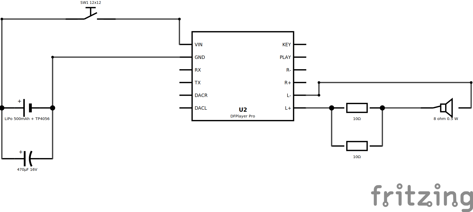
| Speaker | Visaton K 40, 1 W, 6.85 | 8 Ω 0.5 W, 0.60 | player's amp (~1 W into 8 Ω on a full cell, estimate) is 2x speaker rating | R1 ∥ R2 = 2 x 10 Ω (0.25) → 5 Ω in series: ≤ 0.38 W in speaker, −4 dB; wire-bridge R1 if too quiet |
| Charger | DFR0667 0.5 A, 6.55 | TP4056 micro-USB, 0.85 | ships at 1 A (R_PROG 1.2 kΩ) = 2C on a 500 mAh cell, ~1.3 W heat in closed wood | swap R_PROG to 3.3 kΩ (0.25) → 0.36 A (0.7C, ~0.5 W, 1.5–2 h); verify 1.2 kΩ pin 2→GND first (some arrive ~800 Ω) |
| Battery | Akyga 503040 550 mAh, 4.56 | GeB 503035 500 mAh, 4.01 | max discharge 0.25 A (0.5C) < peaks → voltage dips | C1 470 µF 16 V (0.16) across battery, before the button (after it, each press would dump the cap through the 50 mA tact switch) |
| Player | 12.31 | 11.20 | none, same DFR0768 | – |
| Headers | 1x6 x2, MOQ 10 = 0.90 | 1x40 strip cut in two, 0.20 | check 8.5 mm height | – |
| Button | Omron B3F-4000, 0.30 | 12 x 12 x 4.3 mm, 0.08 | unbranded | same footprint/height; same 50 mA caveat as v6 |
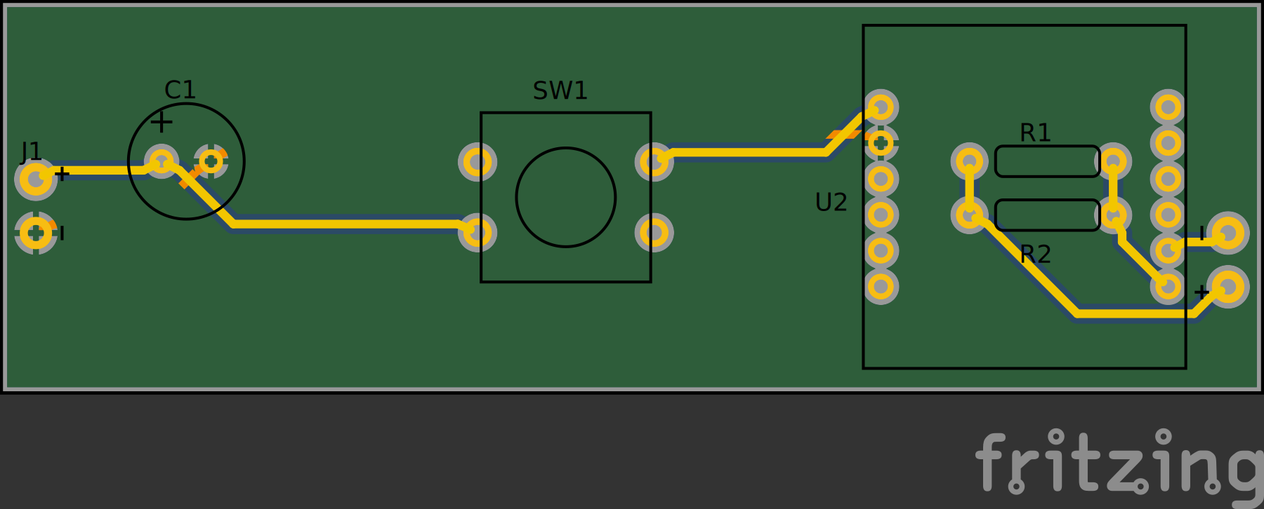
- added parts total 0.66 EUR (C1, R1/R2, R_PROG) → cheaper parts stay cheaper; USB-C charger variant rejected: lacks the 5.1 kΩ CC resistors, charges only from A-to-C cables
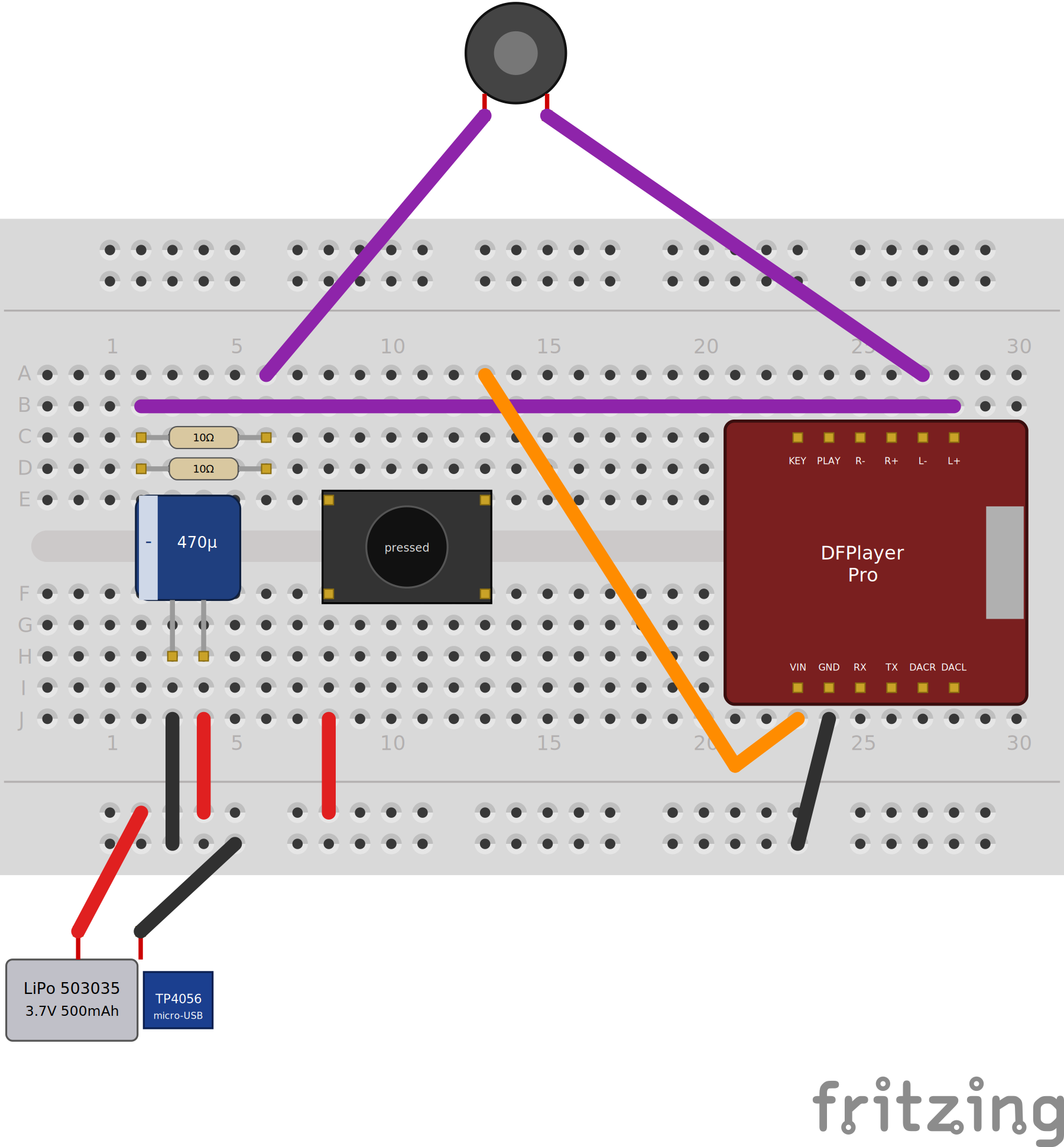
- 6 nets (breadboard, PCB, Gerbers); same outline, enclosure unchanged (C1 no taller than v5's C2; R1/R2 sit under the module → solder R1, R2 first, then SW1, C1, headers, J1/LS1 wires)
- status: designed + simulated (module 3.69 V, 0.5 V across R1∥R2, 0.8 V across speaker), not yet built; all loudness, charge-current and heat figures are calculations to confirm on the bench
v7 schematic, breadboard and PCB
KNIFE-006 - 2026-10-05 - PCB versions v1–v7: fixes and cost
PCB across versions
| Ver | Date | Size (mm) | Parts on board | Nets | Core change |
|---|---|---|---|---|---|
| v1 | 09-27 | 84.0 x 62.0 | DFPlayer Mini, ATtiny85, AO3401A, passives, 16340 | – | baseline sent to fab-feasibility review |
| v2 | 09-27 | 52 x 37 | v1 + R4, C3 | – | −63 % area, 12 mil rules, GND pour, RST pull-up, decoupling |
| v3 | 09-27 | 78.1 x 26.7 | v2 + coin holder, C2 | 12 | bird-belly strip, sleep firmware, CNC enclosure |
| v4 | 09-27 | 89.4 x 27.9 | 13 | – | techfun.sk: Digispark, DFPlayer Pro, NDP6020P, LiPo + TP4056 |
| v5 | 09-28 | 89.4 x 27.9 | 13 + socket + headers | 11 | TME: bare ATtiny85, SOT-23 MOSFET, SPICE + breadboard view |
| v6 | 10-01 | 89.4 x 27.9 | 4 | 5 | MCU removed, button in battery line |
| v7 | 10-03 | 89.4 x 27.9 | 7 | 6 | techfun.sk + LaskaKit, C1 + R1/R2 compensate |
Issues → fix
| Issue | Found | Fixed in |
|---|---|---|
| Floating RESET, no DFPlayer decoupling | v1 review | v2 (R4, C3) |
| Board 84 x 62 mm, does not fit the bird | v1 | v2 52 x 37 → v3 78.1 x 26.7 strip |
| Coin cell / AO3401A / 3 W speaker not sold at techfun.sk | v3→v4 | v4 LiPo + TP4056, NDP6020P, 0.5 W speaker |
| USB back-feed, Digispark LED + zener leakage | v4 | v5 bare chip |
| NDP6020P, Digispark, 30 x 30 LiPo, USB-C chargers unavailable at TME | v5 | v5 substitutions, longer LiPo pocket (41 x 31 x 6) |
| LED 330 Ω wastes battery | v5 | R3 = 1 kΩ (~2 mA) |
| Simulator segfault, no breadboard, battery smoke, invisible traces | v5 | SPICE models, breadboard, J1 fix, coloured fills |
| MCU + programmer for one on/off function | v5 | v6 |
| Cost with TME | v6 | v7 |
Cost per bird (shop prices, shipping excluded)
| Ver | Shop | Total | Note |
|---|---|---|---|
| v4 | techfun.sk | not priced | |
| v5 | TME | ≈ 34 USD + ATtiny85 (~1.5–2) | + 19.51 programmer if needed |
| v6 | TME | ≈ 31.50 USD | |
| v7 | techfun.sk + LaskaKit | ≈ 17.60 EUR incl. VAT | two shipments |
- firmware: v3 sleep → v4 DFPlayer Pro AT commands → v5 bare ATtiny85 (720 bytes, never run on hardware) → v6/v7 none
- 2026-10-05: first Blender CNC model (
smvit-cnc.blend) added; Nightjar enclosure has needed only one re-cut since v4 (v5 LiPo pocket), because the outline, battery pads, button and module were frozen from v4 on - open: build one v7 and measure boot delay, loudness at full volume, charge current/heat, standby; v7 and v6 not hardware-tested; v4+ put a Li-ion charger module inside the wood while CR-04 said "no charging inside" and the PTC/thermal fuse are not on the v4–v7 boards → decide before gluing the enclosure
📊 Prehľady KNIFE príspevkov
Tu nájdeš rýchle odkazy na prehľady všetkých KNIFE záznamov podľa rôznych pohľadov:
- 📰 Blogový prehľad — zoradený podľa ID s dátumom vytvorenia.
- 🗂️ Zoznamový prehľad — stručný zoznam so statusom a prioritou.
- 📈 Detailný prehľad — tabuľka s ID, dátumom, statusom a prioritou.
📚 Pre návrat na hlavnú stránku dokumentácie klikni na 🧭 Hub